Garrattfan's Modelrailroading Pages

NS 8600 class
Superstructure: running board

In other projects I used to describe the building of the locomotive's superstructure in two separate subjects:
With this kit the first part is greatly simplified because the bulk of the superstructure is supplied in three resin cast parts which will not assembled until after painting. So this I took a different appraoch. Again I have divided the description in two subjects
The running board and the detailing of the resin parts are more or less built in parallel.
|
|
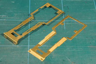 |
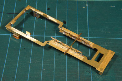
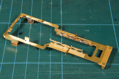
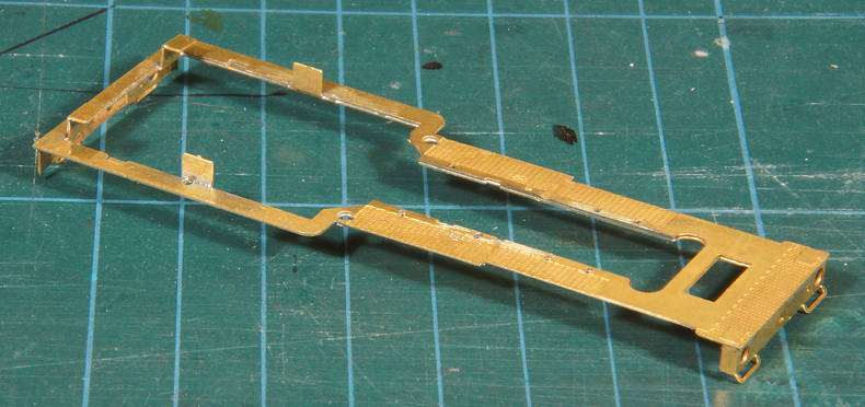
The chassis had a broken wheel so I ordered a spare from Fleischmann. While waiting for that part to arrive I started with the superstructure. The etch contains two major parts, one with a fish plate relief on it (right) and one without (left). The one without the relief is folded as shown (instructions 14-16). Both etches proved to be very delicate, if not downright flimsy. For one the structure is very narrow at places, but the brass used for these etches is very soft. Too soft to my taste. I have seen equally delicate structures etches in stronger brass and that worked very well. But these two caused a great deal of annoyance throughout the build. So take great care not to deform them. |
 |
Getting the two etches together needs some careful work. First check, check and check over and over again that both etches are perfectly flat. Correct if necessary. Do NOT be tempted to think that any roughness in the etches will sort itself out while joining the two. Get it sorted out now. I used a tempered glass pane for that purpose, a glass shelf from an old refrigerator. This glass pane is absolutely flat and can be used as a reference. Work on the etches carefully. Do not drop or bump them or you can can start all over again. Guess why I tell you!
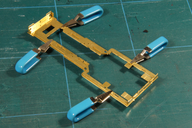
Once they were flat I clamped them with four self-closing mini-clamps I once bought from MicroMark (item # 60928). Place one clamp and move the etches until they line up correctly then add the other three, checking every time that the etches are still aligned. |
Intermezzo construction methodsThe kit is designed for both gluing and soldering, says the manual. I recommend soldering. I use three methods of joining, in order of preference:
Learn to solder is my motto. If you are afraid of soldering, many people daunt the prospect, this is your chance to acquire dearly needed skills if you intend to build more models in the future. That being said it is obvious that I will solder the two etches.
|
|
 |
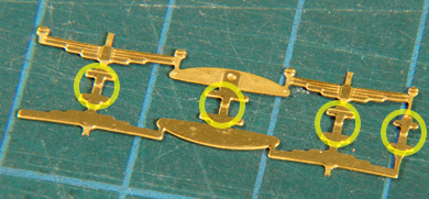
That raises another issue. If you solder the whole piece in one go and work your way around (counter)clockwise, the workpiece will distort because of the uneven application of heat. To prevent that I placed four solder tacks on the workpiece (circles) letting the workpiece cool down after every tack. Then I removed the clamps and checked for the very last time if the two etches were well aligned. Then I started filling in with short solder seams. Again not long stretches in one go. From a tack to the corner. Then on the other side from a tack to the corner etc. Never in stretches of more than a few centimetres and criss-crossing the solder work over the workpiece. Every time I allowed the workpiece to cool down until I could hold it. This prevents the build up of heat and willkeep the workpiece straight. After soldering the workpiece is cleaned with water and a brush to remove any remaining flux. |
The tabs are raised and soldered in the fold to strengthen. The manual recommends to bend the tabs first and then solder the two main parts together. I turned that around so I work on the running board lying flat on the soldering mat. |
|
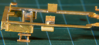
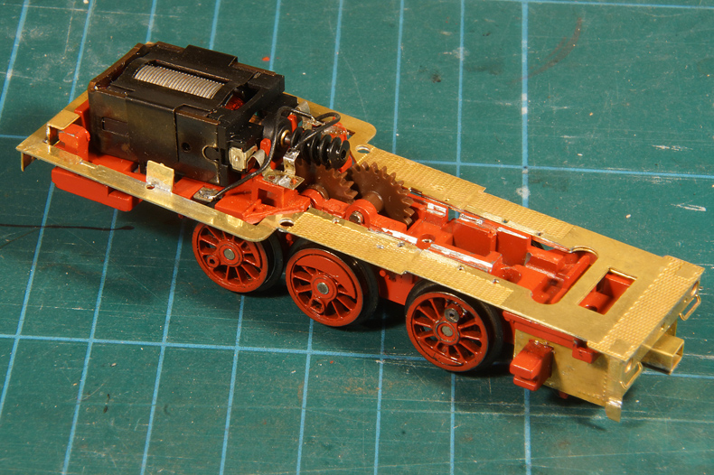
A test fit on the chassis. |
|
 |
Funnily the manual remarks not to take parts out of the etch until they are really needed, but once you take out the two running board etches this is the remainder of the etch :-) |
 |
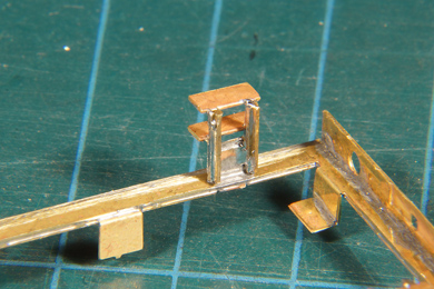
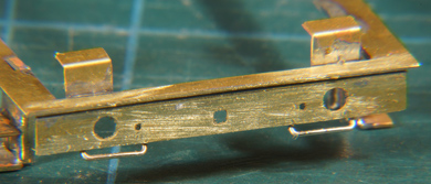
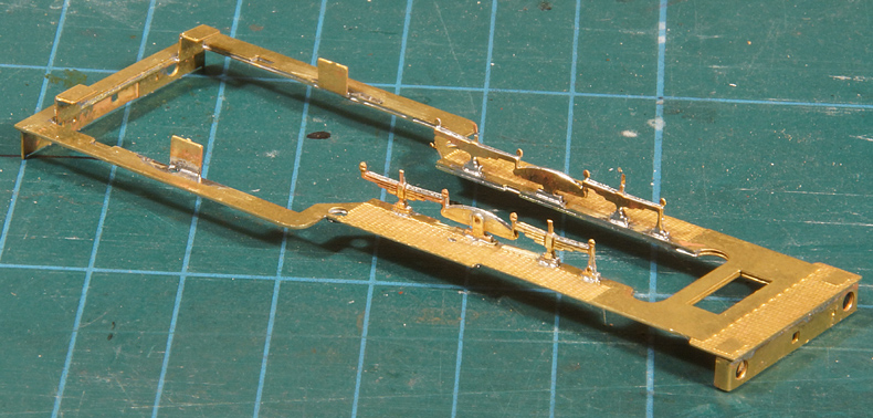
The norm is that a fold line is on the inside of the fold. The one exception is however that it is on the outside if the etch is to be folded all over 180 degrees. The spring assembly is such an etch. Again the soft brass makes it difficult to keep the etch flat while folding over, so once folded check if it is really flat and correct if needed. Then I soldered the spring assembly. |
The spring assemblies in place. |
|
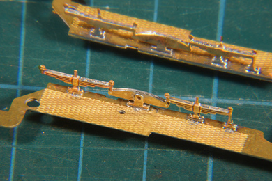 |
See to it they sit absolutely square on the running board and then solder from the back paying attetiton to the good flow of the solder. I could solder the spring assembly on the running board with 180C solder without a budge. Just, but that is genereally so, do not linger too long with iron. After soldering the etch cusps are carefully filed where they visible, on the top of the springs and the balances. |
Intermezzo solderingThe risk of soldering is that a previously soldered join comes loose while you solder the next one. Cooling is one solution. Cover the exisiting join by wrapping it in a shred of wetted kitchen paper. As long as the water is present, the join will not heat over 100C. You can also use stepped soldering: using solders of different melting points. I have 240C, 180C, 140C and 80C solder. I prefer to limit that to situations where it is absolutely necessary. I use 180C as a standard. Once you get the hang of soldering you will be amazed what you can do without stepped soldering.
Let's continue |
|
 |
 |
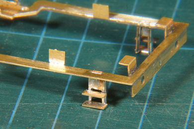
The steps under the driver's cab are added. Again the soft brass played havoc while working on the steps. I strengthened the steps by soldering pieces of hardened brass profile behind them. The soldering job isn't neat but it does the trick and will be next to invisible anyway |
|
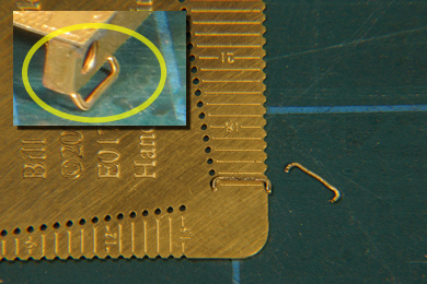 |
The brass grab irons in the buffer area of the running board were snipped off. Very thoughtful of the kit manufacturer to include them in the etch of the running board but it is useless in practise.
|
 |
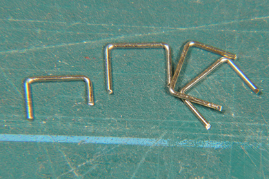 |
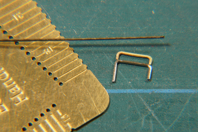
| So I made my own from nickel silver. I measured the original grab iron (top) on my handrail bending jig (by Bill Bedford Models) and replicated it with nickel silver wire (0.5 mm) and before long I had four identical grab irons | |
 |
 |
They were soldered in place. I used a piece of scrap nickel silver to get and even spacing and to help with handling the tiny parts. I left a small stub from the original etched iron to indicate the location for the new iron. |
|
 |
After soldering they are bent forward by 45 degrees. |
 |
Toolbox etch soldered in place |
Check occasionally for squareness, in this case on two identical wooden blocks. Laid flat it should not wobble on any of its four corners.
|
|
Buffers are trial fitted. I did not use the supplied resin buffers but sprung buffers from Philotrain. In later life the 8600 class had this longer model buffers.
|
|
 |
 |
| I forgot to add the rod for the motion gear, so I corrected that omission now. | |
 |
Lamp added. The buffer plates are glued, so I had no other option than to glue the lamp as well. I opted to add only one lamp, signifying that the loco is doing shunting manoeuvres, because that is what the loco did for most of its life. |
 |
Small tank added |
 |
|
The water fill pipes are ugly things with their funnels on top, protruding well above the water tanks. They gave me headache how to mount them on the running board.
So I gave it a good thought how I could best assemble the water fill pipes and came up with an old trick which I used to repair my NS 7851: reinforcing the join by adding a firm nickel silver rod inside the fill pipe before gluing. |
|
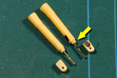 |
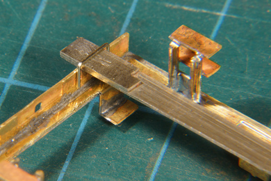
Like this. The nick silver is 0.8 mm wide. The middle of the spigot that is supposed to go in the hole in the running board is shortened to sit flush with the underside of the running board (yellow arrow). I then carefully marked the middle of the underside of the spigot. A good eye is real help here. It is then dilled and the nickel silver wire is glued into the filler pipe. The spigot in the part below the running board is cut short but not filed away yet. Again the middle is determined, a hole drilled entirely through the part and only then the remainder of the spigot is filed flat. I combined the sets of parts to see which combination gave the best result, after all you are never 100% accurate, and I marked one set. |
 |
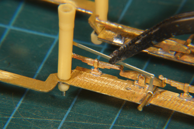
Then I offered the fill pipe up to the running board, clamped the nickel silver rod and carefully lined out the fill pipe by moving the clamp around so the pipe would sit vertical, taking a square as a reference (below left) for longitudinal position and the surface of the vise (below right) for lateral orientation |
 |
 |
 |
After allowing the expoxy glue to set for ten minutes I added the other fill pipe in a similar way. After another ten minutes I added the parts under the running board and again allowed ten minutes for the epoxy glue to set.
Yes, working with epoxy is a slow process, so I always have something to do at hand (like updating my website on the progress). |
 |
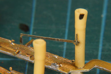
Note that I have marked the fill pipes at the top end (both are marked but the mark on the right hand pipe is hardly visible. That is to mark the orientation of the funnel. The black dot is supposed to point back under an angle of about 45 degrees so that the funnel points outwards.
Photos of the prototype show these funnels to point in random directions so they were probably loose on top of the filler pipe. The funnels were a later addition as early photos do not show them. |
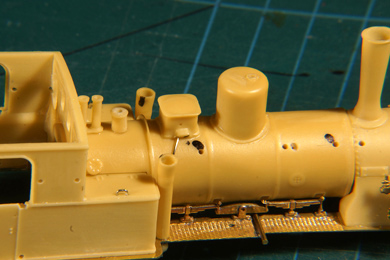 |
Now the body is fitted... |
 |
...and a last check is made.
Epoxy glue sets "in five minutes", so claims its manufacturer. Reality is that it remains sticky and mallable for about an hour getting increasingly viscous. This viscosity has a will of its own so it is a matter of prudence to check after some time if the parts are still in place as you intended.
I did and the right hand pipe (left on the photo) was a bit off. Pushing it back is not enough as the setting glue soon takes over again forcing the filler pipe back out. So I secured the pipe with a dot of Blu-Tack and left it until the next day. |
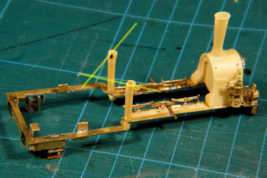
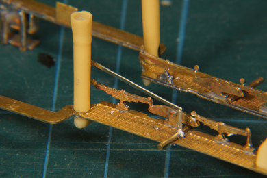
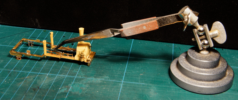
The reverse lever is soldered to the reverse shaft. It is a very flimsy part but thankfully it was included in the nickel silver etch, which is much harder than the brass etching included in the kit. Again I made good use of the self-closing tweezers. |
|
 |
 |
 |
In reality it runs behind the filler pipe into the cab but in the kit it ends behind the filler pipe. With a bit of epoxy I secured the other end on the filler pipe. This turned out to be too vulnerable. When I resumerd work after the glue had I knocked it loose within minutes. So I drilled a hole in the filler pipe below the lever, glued an angled nickel silver rod in the hole and kind of hung up the lever, glued on both sides. The rod will be as good as invisible once the boiler and cab are in place. |


Sign my
GuestBook